
15Chapter 15 of 51
Create a URDF Model
In this tutorial, we will create a complete URDF model of a mobile robot using ROS 2 and Xacro.
We will build the robot step by step, starting from the ROS 2 package and robot description files, then adding the base, drive wheels, and caster wheels.
Along the way, we will understand how links, joints, origin, xyz, and rpy are used to describe the robot’s structure and position.
By the end, we will visualize the complete robot and understand its kinematic tree.
Create the ROS 2 Package
The first step is to create a ROS 2 package that will contain our robot description.
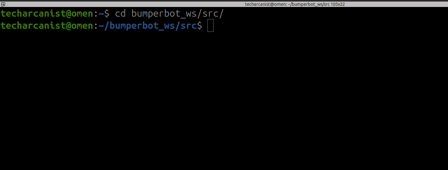
Open a terminal and navigate to the src folder of the workspace.
cd bumperbot_ws/src/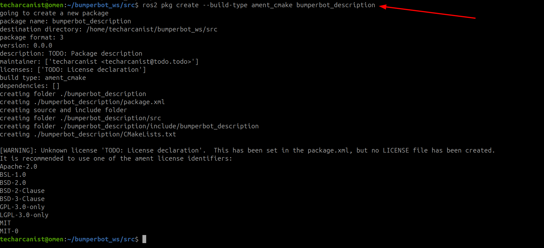
Now create a new ROS 2 package named bumperbot_description using the ament_cmake build system.
This creates the bumperbot_description package that will contain all the files required to describe our robot.
ros2 pkg create --build-type ament_cmake bumperbot_description
Move back to the workspace directory:
cd ..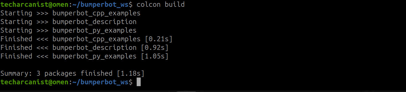
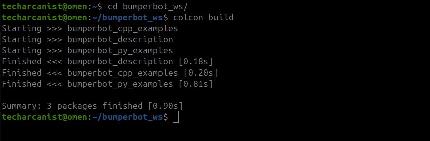
Now build the workspace:
colcon buildThe workspace has now been built successfully.
Next, we will create the folders required for our robot description.
Create the URDF Folder
Create the URDF and Mesh Folders
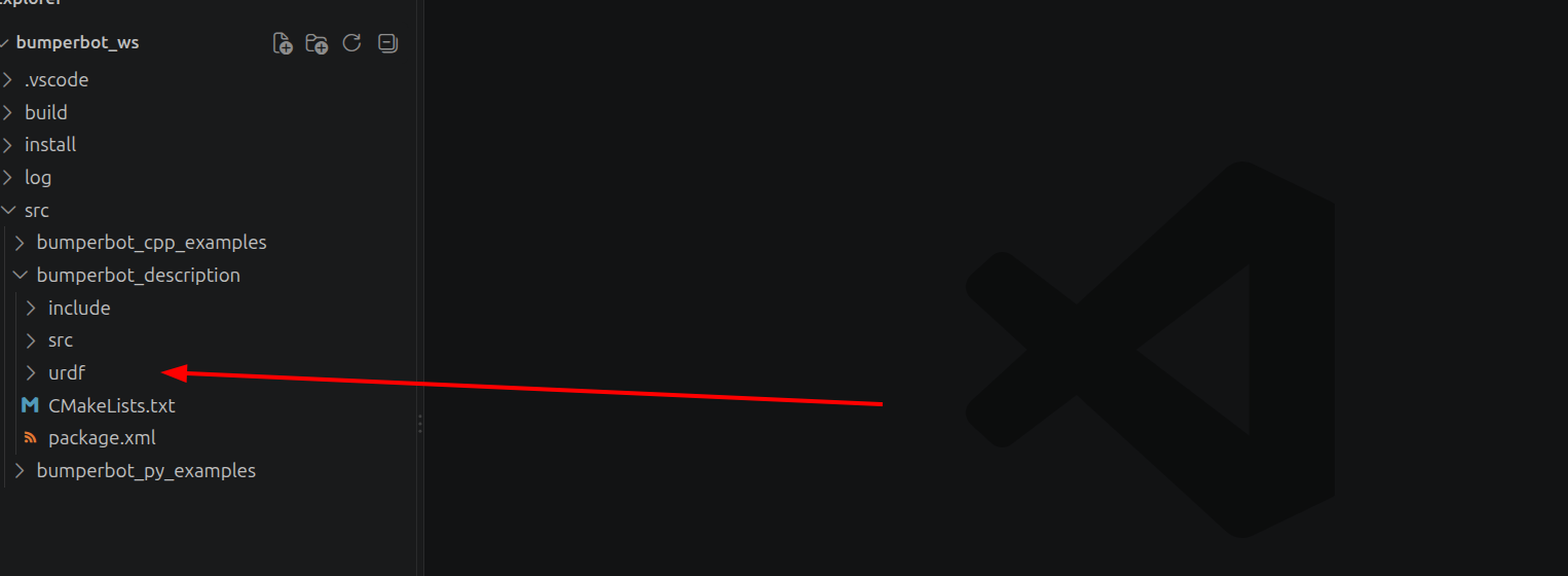
Inside the bumperbot_description package, create a folder named urdf.
The urdf folder will contain the robot description file.
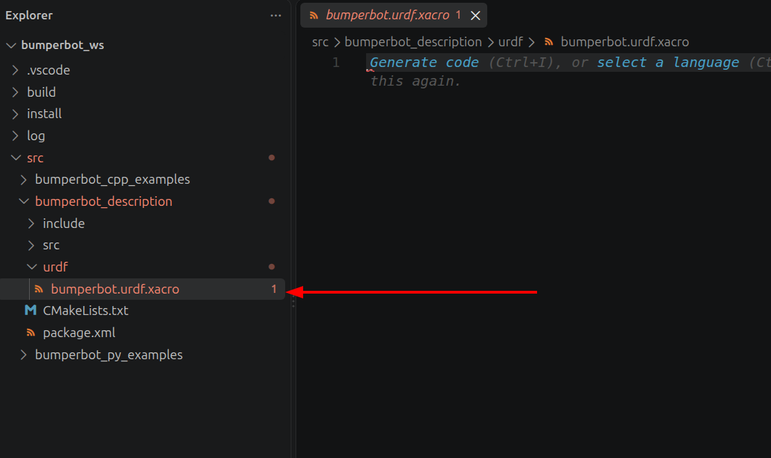
Inside the urdf folder, create a file named:
bumperbot.urdf.xacroWe will use this Xacro file to define the structure of our robot.
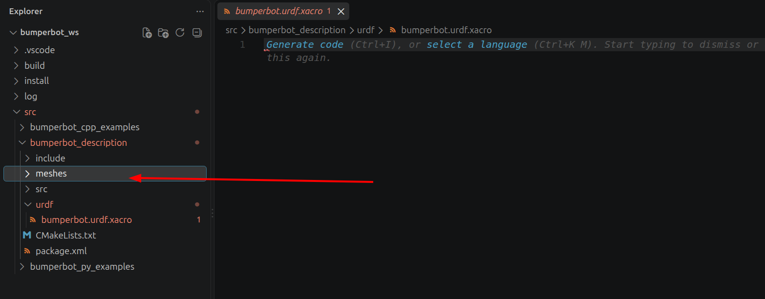
Now create another folder inside bumperbot_description named meshes.
The meshes folder will contain the STL files used for the visual representation of the robot.
Download the STL and Gazebo files using the link below.
Download the ZIP file and extract it.
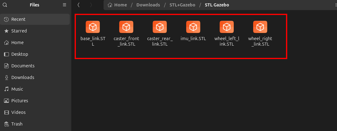
Copy all the STL files from the extracted folder.
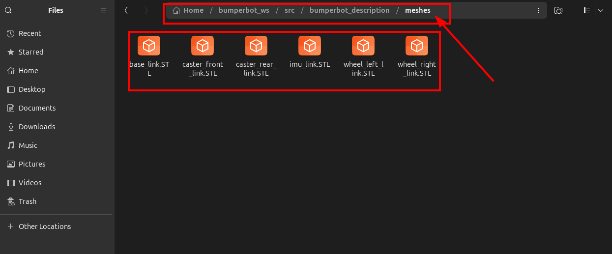
Paste all the STL files inside the meshes folder.
Create the Base Robot
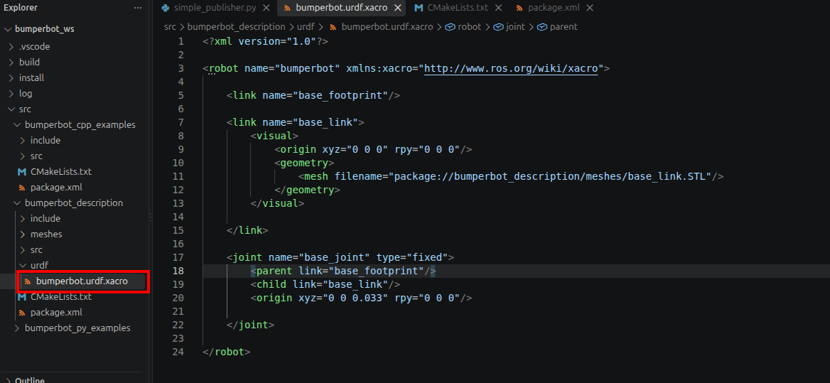
Now open bumperbot.urdf.xacro in Visual Studio Code and add the following code.
<robot name="bumperbot" xmlns:xacro="http://www.ros.org/wiki/xacro">
<link name="base_footprint"/>
<link name="base_link">
<visual>
<origin xyz="0 0 0" rpy="0 0 0"/>
<geometry>
<mesh filename="package://bumperbot_description/meshes/base_link.STL"/>
</geometry>
</visual>
</link>
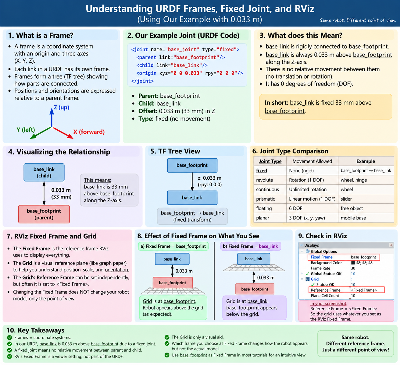
<joint name="base_joint" type="fixed">
<parent link="base_footprint"/>
<child link="base_link"/>
<origin xyz="0 0 0.033" rpy="0 0 0"/>
</joint>
</robot>Why is the Base Link 33 mm Above the Base Footprint?
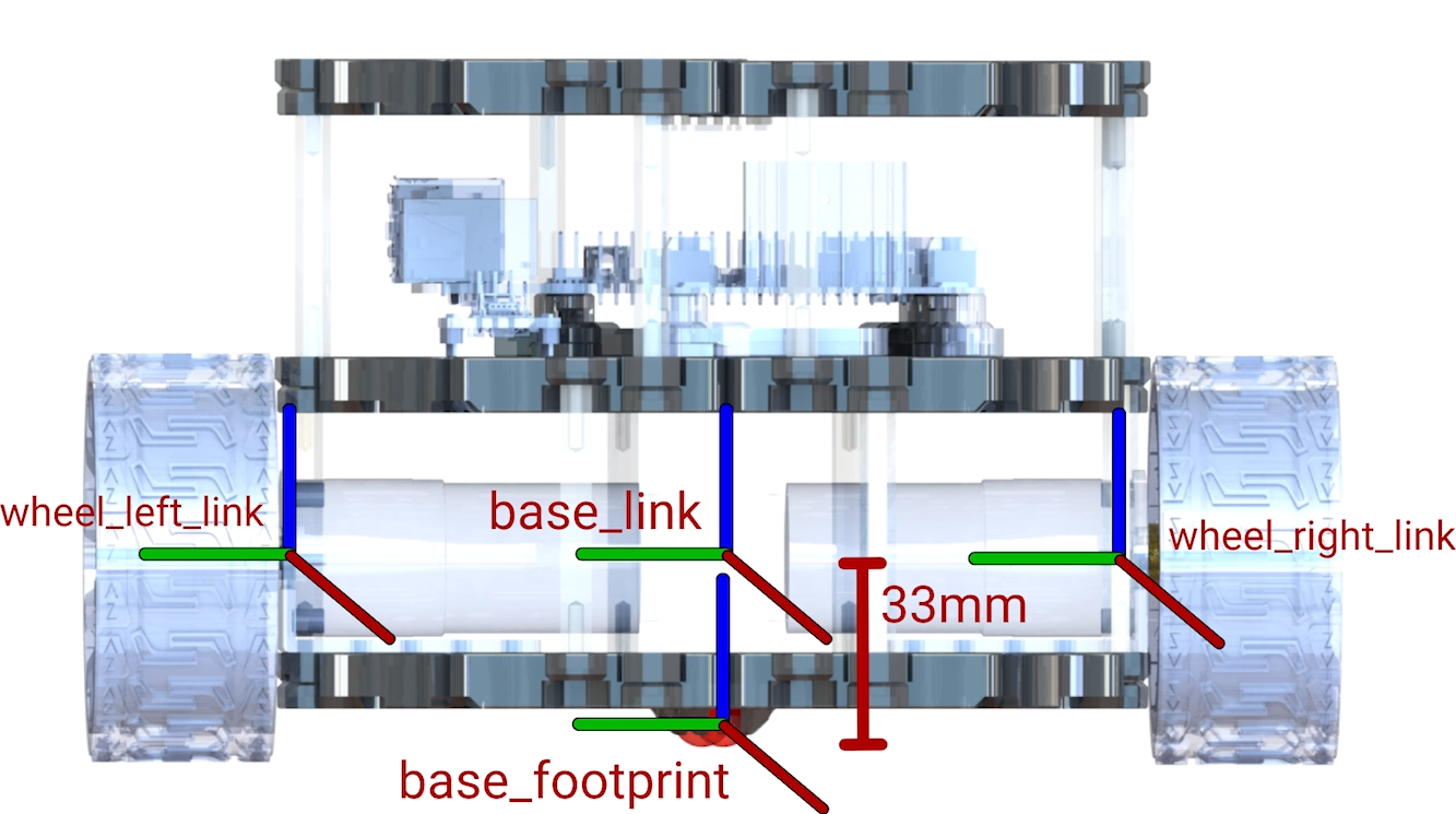
In the CAD model of our robot, the base footprint is located at the middle of the robot, at its lowest point where the robot makes contact with the ground.
The base link has the same orientation as the base footprint, but it is positioned higher and passes through the axis of the robot’s wheels.
From the 3D model, we can see that the base link is 33 mm above the base footprint.
Since the base footprint and base link have the same orientation, there is no relative rotation between them, so we set the rotation values to zero.
The base footprint is taken as the reference point. Therefore:
- X = 0
- Y = 0
- Z = 0.033 m = 33 mm
- Roll = 0
- Pitch = 0
- Yaw = 0
Install the URDF and Meshes
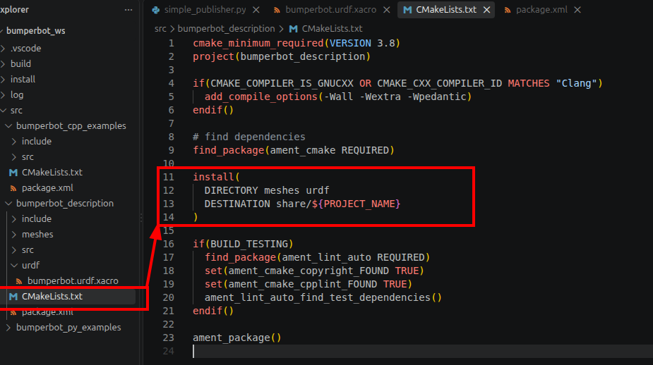
install(
  DIRECTORY meshes urdf
  DESTINATION share/${PROJECT_NAME}
)
This installs both the meshes and urdf directories into the package’s shared installation directory.
Now go back to the workspace and build the package again.
cd bumperbot_ws/
colcon build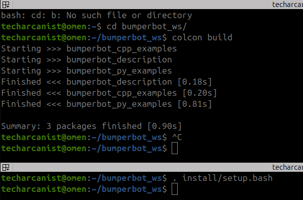
After the build completes, source the workspace so that ROS 2 can find the updated package.
. install/setup.bashVisualize the Robot
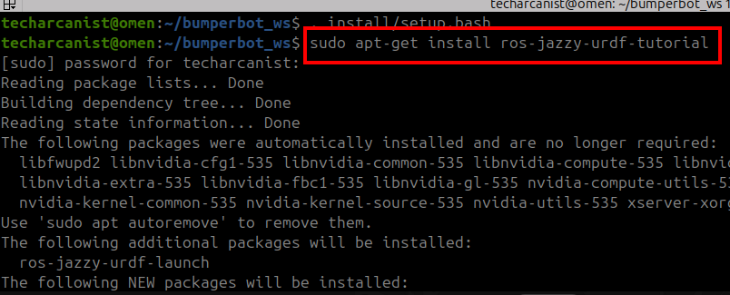
To display our robot model, we first need to install the ROS 2 URDF tutorial package.
sudo apt-get install ros-jazzy-urdf-tutorial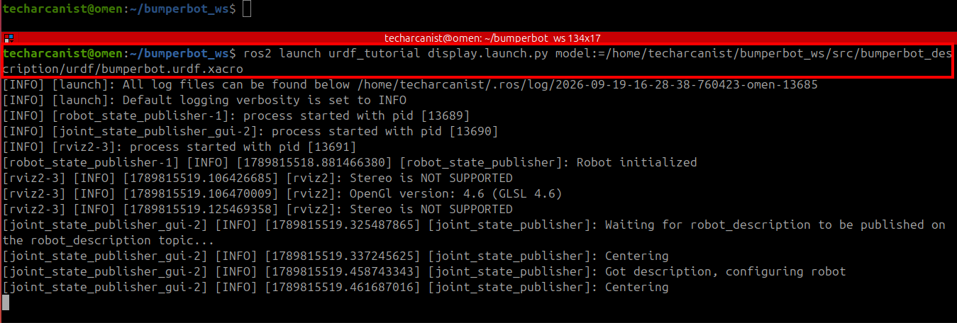
Once the package is installed, launch the URDF visualization using:
ros2 launch urdf_tutorial display.launch.py model:=/home/techarcanist/bumperbot_ws/src/bumperbot_description/urdf/bumperbot.urdf.xacroThis command opens the URDF visualization and displays the robot model.
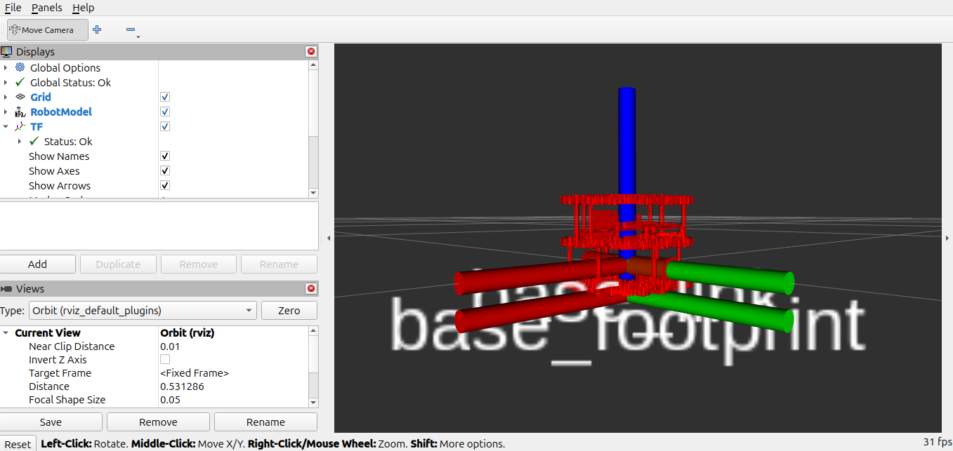
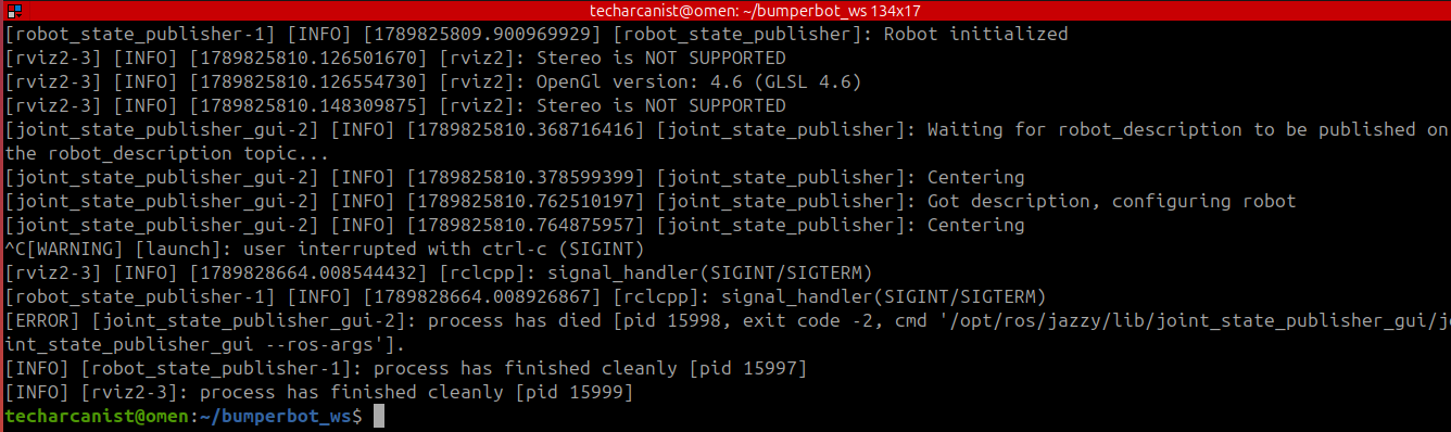
The base of the robot is now visible in the visualization.
Press Ctrl+C to close the current visualization. We can now move on to adding the wheels.
Add the Right Wheel
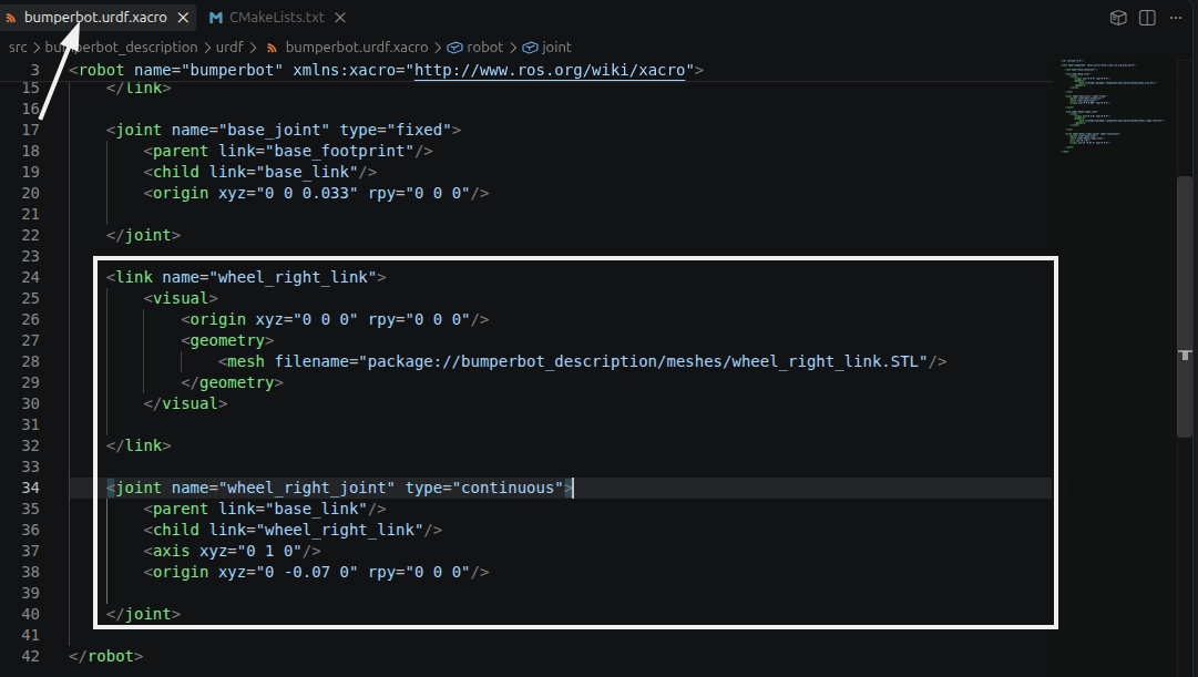
Now we will add the right wheel to the robot.
Open bumperbot.urdf.xacro and add the right wheel link and joint.
<robot name="bumperbot" xmlns:xacro="http://www.ros.org/wiki/xacro">
<link name="base_footprint"/>
<link name="base_link">
<visual>
<origin xyz="0 0 0" rpy="0 0 0"/>
<geometry>
<mesh filename="package://bumperbot_description/meshes/base_link.STL"/>
</geometry>
</visual>
</link>
<joint name="base_joint" type="fixed">
<parent link="base_footprint"/>
<child link="base_link"/>
<origin xyz="0 0 0.033" rpy="0 0 0"/>
</joint>
<link name="wheel_right_link">
<visual>
<origin xyz="0 0 0" rpy="1.57 0 0"/>
<geometry>
<mesh filename="package://bumperbot_description/meshes/wheel_right_link.STL"/>
</geometry>
</visual>
</link>
<joint name="wheel_right_joint" type="continuous">
<parent link="base_link"/>
<child link="wheel_right_link"/>
<axis xyz="0 1 0"/>
<origin xyz="0 -0.07 0" rpy="0 0 0"/>
</joint>
</robot>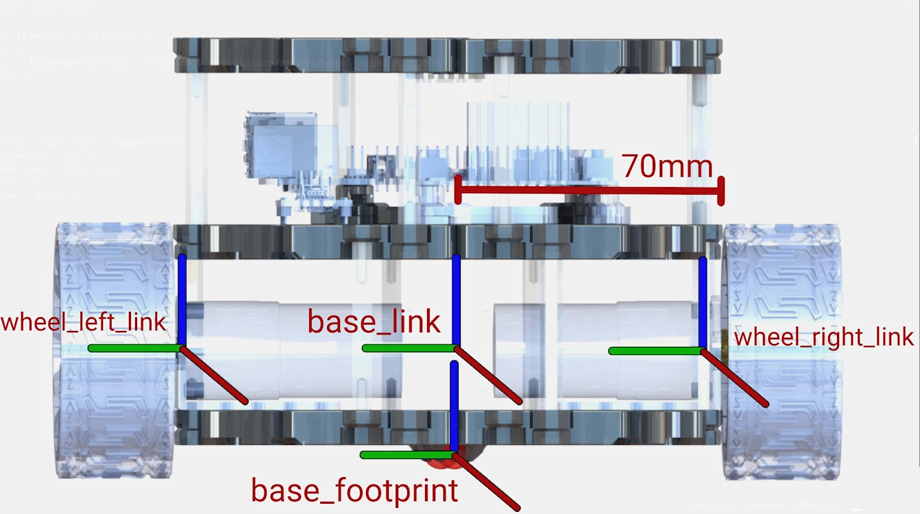
In the CAD model, the right wheel is positioned 70 mm away from the reference origin.
Since 70 mm is equal to 0.07 m, we use:
<origin xyz=”0 -0.07 0″ rpy=”0 0 0″/>
Visualize the Right Wheel
Save the Xacro file and run the visualization command again:
ros2 launch urdf_tutorial display.launch.py model:=/home/techarcanist/bumperbot_ws/src/bumperbot_description/urdf/bumperbot.urdf.xacro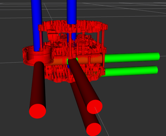
As we can see, the wheel has been added, but its orientation is not correct.
Correct the Wheel Orientation
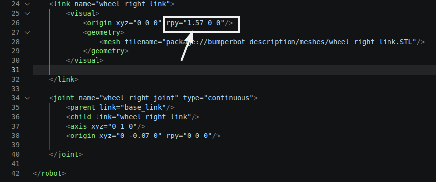
The wheel mesh needs to be rotated so that it is correctly aligned with the robot.
URDF uses radians for rotational values.
The commonly used degree-to-radian conversions are:
| Degrees | Radians |
|---|---|
| 0° | 0 |
| 45° | 0.7854 |
| 90° | 1.5708 |
| 180° | 3.1416 |
| -90° | -1.5708 |
<origin xyz="0 0 0" rpy="1.57 0 0"/>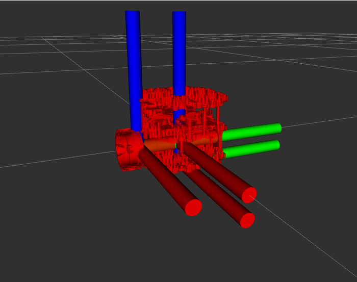
After applying the rotation, the wheel is now correctly aligned with the robot.
Add the Left Wheel
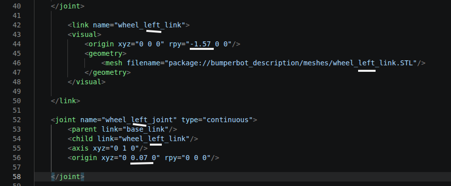
Now that the right wheel is correctly positioned and oriented, we can add the left wheel in the same way.
The left wheel is placed on the opposite side of the robot, so its Y position and visual rotation are mirrored.
The left wheel uses:
+0.07 mon the Y-axis for its position.-1.57radians for its visual orientation.
<robot name="bumperbot" xmlns:xacro="http://www.ros.org/wiki/xacro">
<link name="base_footprint"/>
<link name="base_link">
<visual>
<origin xyz="0 0 0" rpy="0 0 0"/>
<geometry>
<mesh filename="package://bumperbot_description/meshes/base_link.STL"/>
</geometry>
</visual>
</link>
<joint name="base_joint" type="fixed">
<parent link="base_footprint"/>
<child link="base_link"/>
<origin xyz="0 0 0.033" rpy="0 0 0"/>
</joint>
<link name="wheel_right_link">
<visual>
<origin xyz="0 0 0" rpy="1.57 0 0"/>
<geometry>
<mesh filename="package://bumperbot_description/meshes/wheel_right_link.STL"/>
</geometry>
</visual>
</link>
<joint name="wheel_right_joint" type="continuous">
<parent link="base_link"/>
<child link="wheel_right_link"/>
<axis xyz="0 1 0"/>
<origin xyz="0 -0.07 0" rpy="0 0 0"/>
</joint>
<link name="wheel_left_link">
<visual>
<origin xyz="0 0 0" rpy="-1.57 0 0"/>
<geometry>
<mesh filename="package://bumperbot_description/meshes/wheel_left_link.STL"/>
</geometry>
</visual>
</link>
<joint name="wheel_left_joint" type="continuous">
<parent link="base_link"/>
<child link="wheel_left_link"/>
<axis xyz="0 1 0"/>
<origin xyz="0 0.07 0" rpy="0 0 0"/>
</joint>
</robot>Save the file and visualize the robot again to check the alignment.
ros2 launch urdf_tutorial display.launch.py model:=/home/techarcanist/bumperbot_ws/src/bumperbot_description/urdf/bumperbot.urdf.xacro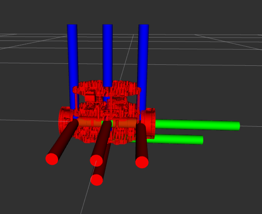
The left wheel is now correctly positioned.
Both drive wheels are now correctly aligned with the robot.
Add the Caster Wheels
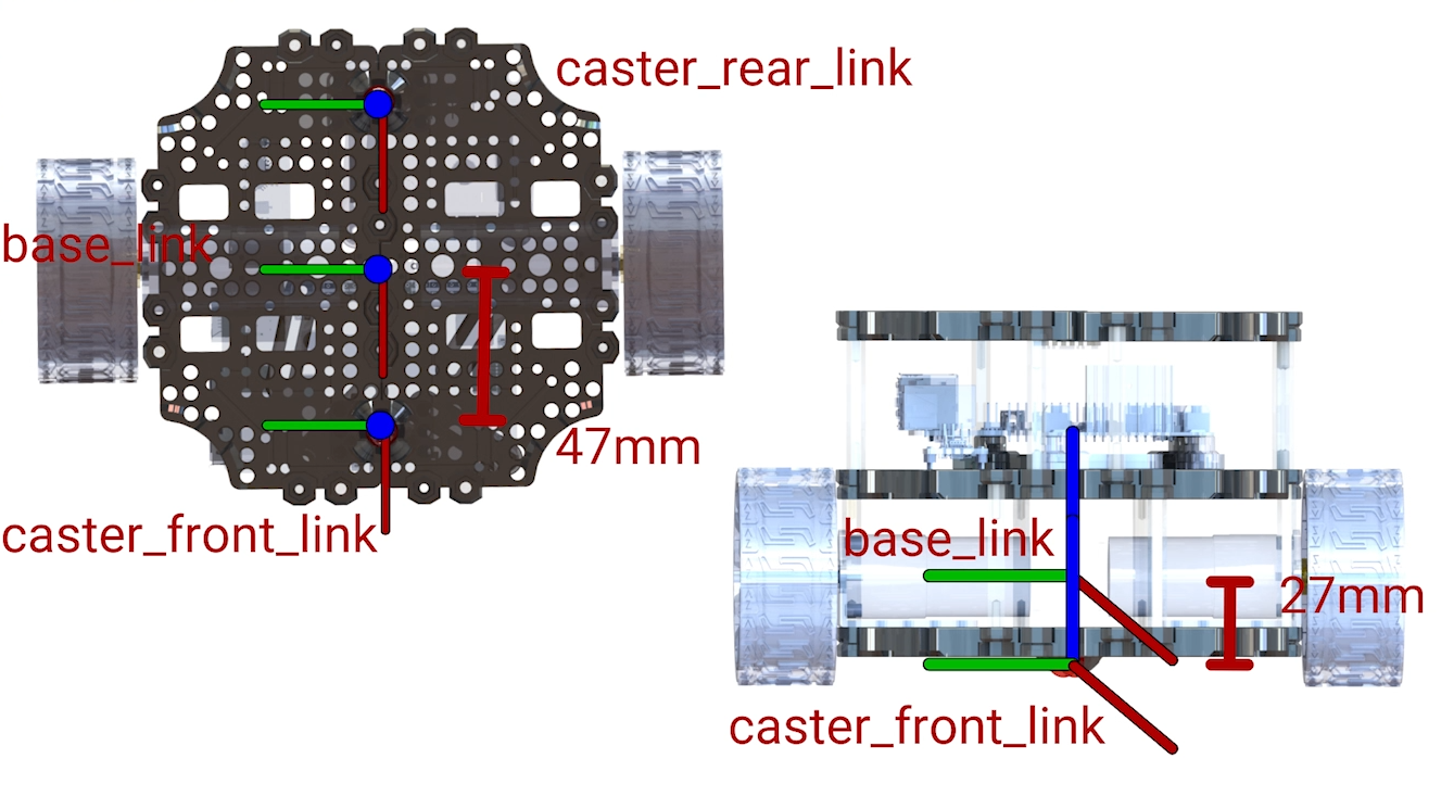
The robot also has two caster wheels: one at the front and one at the rear.
These caster wheels are connected to the base_link using fixed joints.
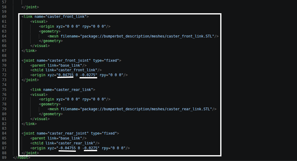
The caster wheel positions are taken from the CAD model relative to the base_link.
<robot name="bumperbot" xmlns:xacro="http://www.ros.org/wiki/xacro">
<link name="base_footprint"/>
<link name="base_link">
<visual>
<origin xyz="0 0 0" rpy="0 0 0"/>
<geometry>
<mesh filename="package://bumperbot_description/meshes/base_link.STL"/>
</geometry>
</visual>
</link>
<joint name="base_joint" type="fixed">
<parent link="base_footprint"/>
<child link="base_link"/>
<origin xyz="0 0 0.033" rpy="0 0 0"/>
</joint>
<link name="wheel_right_link">
<visual>
<origin xyz="0 0 0" rpy="1.57 0 0"/>
<geometry>
<mesh filename="package://bumperbot_description/meshes/wheel_right_link.STL"/>
</geometry>
</visual>
</link>
<joint name="wheel_right_joint" type="continuous">
<parent link="base_link"/>
<child link="wheel_right_link"/>
<axis xyz="0 1 0"/>
<origin xyz="0 -0.07 0" rpy="0 0 0"/>
</joint>
<link name="wheel_left_link">
<visual>
<origin xyz="0 0 0" rpy="-1.57 0 0"/>
<geometry>
<mesh filename="package://bumperbot_description/meshes/wheel_left_link.STL"/>
</geometry>
</visual>
</link>
<joint name="wheel_left_joint" type="continuous">
<parent link="base_link"/>
<child link="wheel_left_link"/>
<axis xyz="0 1 0"/>
<origin xyz="0 0.07 0" rpy="0 0 0"/>
</joint>
<link name="caster_front_link">
<visual>
<origin xyz="0 0 0" rpy="0 0 0"/>
<geometry>
<mesh filename="package://bumperbot_description/meshes/caster_front_link.STL"/>
</geometry>
</visual>
</link>
<joint name="caster_front_joint" type="fixed">
<parent link="base_link"/>
<child link="caster_front_link"/>
<origin xyz="0.04755 0 -0.0275" rpy="0 0 0"/>
</joint>
<link name="caster_rear_link">
<visual>
<origin xyz="0 0 0" rpy="0 0 0"/>
<geometry>
<mesh filename="package://bumperbot_description/meshes/caster_rear_link.STL"/>
</geometry>
</visual>
</link>
<joint name="caster_rear_joint" type="fixed">
<parent link="base_link"/>
<child link="caster_rear_link"/>
<origin xyz="-0.04755 0 -0.0275" rpy="0 0 0"/>
</joint>
</robot>For the front caster:
X = +0.04755 m
Y = 0
Z = -0.0275 m
For the rear caster:
X = -0.04755 m
Y = 0
Z = -0.0275 m
The X value is approximately 47.55 mm, while the Z value is approximately 27.5 mm.
The positive and negative X values place the two casters at opposite ends of the robot.
Save the Xacro file and visualize the robot again using the same launch command.
ros2 launch urdf_tutorial display.launch.py model:=/home/techarcanist/bumperbot_ws/src/bumperbot_description/urdf/bumperbot.urdf.xacro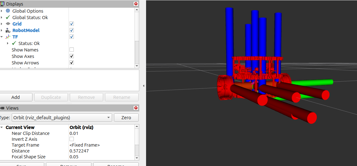
The caster wheels are now correctly positioned, and the complete robot model is visible.