


VISUALIZE THE ROBOT IN RVIZ2
In this chapter, we will use ROS 2 parameters, robot_state_publisher, joint_state_publisher_gui, and RViz2 together to visualize our robot.
The goal is to:
- Publish the robot’s URDF model
- Publish the robot’s joint states
- Visualize the robot’s TF frames
- Display the robot meshes
- Move the wheels using the joint-state sliders
- Save the RViz2 configuration for use later
Note: This practical uses multiple terminals because each ROS 2 node needs to keep running while we work with RViz2.
Source the workspace
Before running our ROS 2 node, we need to source the workspace.

Open a terminal and go to your workspace:
cd bumperbot_ws
Then source the workspace:
. install/setup.bash
Start robot_state_publisher
robot_state_publisher is a general-purpose ROS 2 node that publishes the robot’s state based on its URDF description.
In our case, we need to provide it with the URDF model of our BumperBot.
Our robot model is written using Xacro, so we use the xacro command to convert it into the URDF representation required by robot_state_publisher.
Run:

ros2 run robot_state_publisher robot_state_publisher --ros-args -p robot_description:="$(xacro /home/techarcanist/bumperbot_ws/src/bumperbot_description/urdf/bumperbot.urdf.xacro)"
Understanding the command
The important part is:
--ros-args -p robot_description:=...
Here we are using a ROS 2 parameter to provide the robot description to the node.
The value is generated by:
$(xacro /home/techarcanist/bumperbot_ws/src/bumperbot_description/urdf/bumperbot.urdf.xacro)
So the process is:
bumperbot.urdf.xacro │ │ xacro ▼ URDF model │ │ robot_description parameter ▼robot_state_publisher │ ▼ROS 2 topics
The robot_state_publisher node can then use this robot description to publish the information required to visualize the robot.
Keep this terminal running.
Start joint_state_publisher_gui
Open a new terminal. ctrl+shift+O

Source the workspace again:
. install/setup.bash
Now run:
ros2 run joint_state_publisher_gui joint_state_publisher_gui
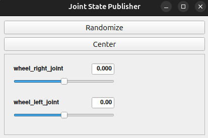
The joint_state_publisher_gui node provides a graphical interface containing sliders for the movable joints of the robot.
For our robot, the GUI contains sliders for:
wheel_left_jointwheel_right_joint
These sliders allow us to change the joint positions manually.
Keep this terminal and the GUI running.
Open Another Terminal for RViz2
Now open one more terminal.
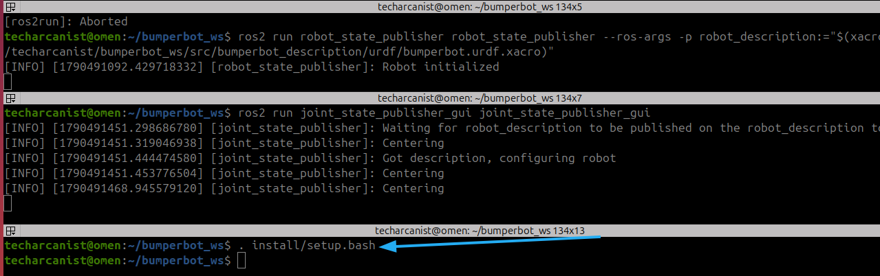
Source the workspace again:
. install/setup.bash
Why do we need another terminal?
At this point we have:
Terminal 1└── robot_state_publisherTerminal 2└── joint_state_publisher_guiTerminal 3└── RViz2
Each node needs to remain running, so we use separate terminals.
Start RViz2
Now start RViz2:
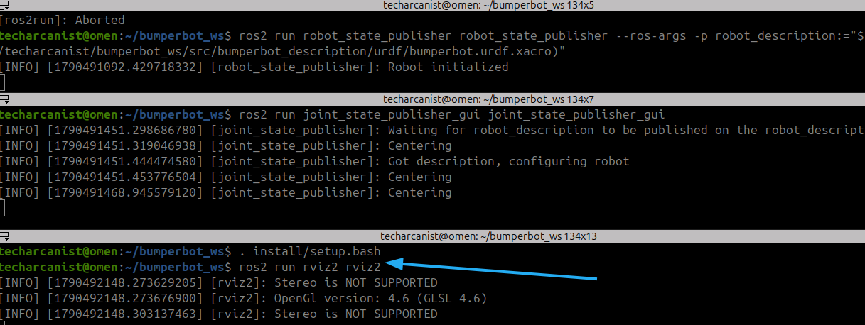
ros2 run rviz2 rviz2
RViz2 will open with its graphical interface.
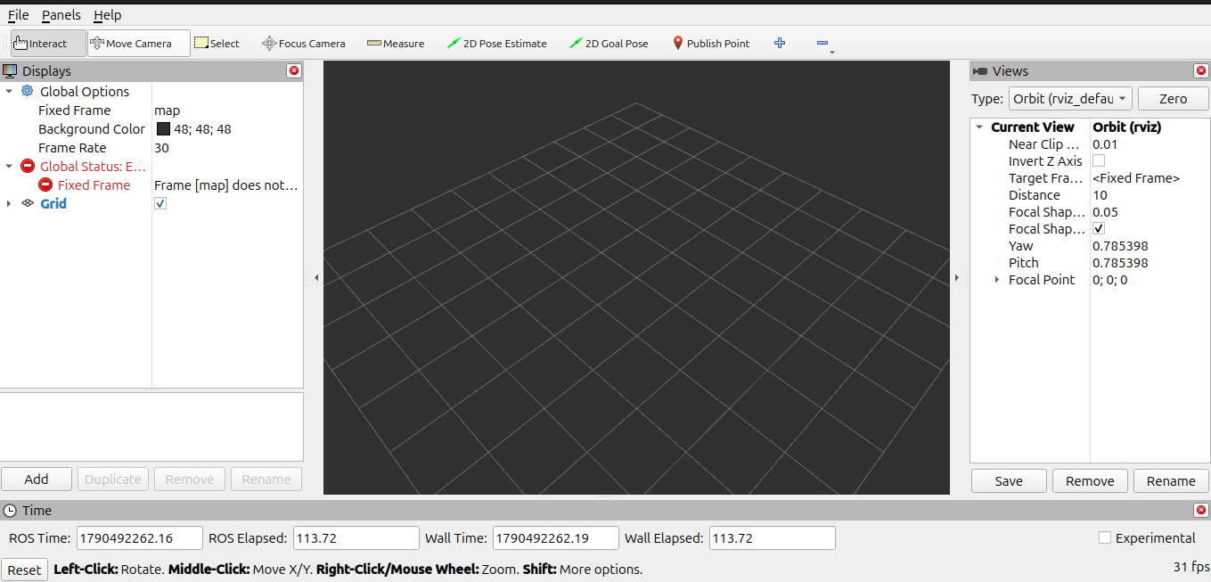
At first, the robot may not be visible and you may see an error related to the map frame.
Fix the Fixed Frame Error

The default Fixed Frame in RViz2 is usually:
map
However, our robot does not currently have a map frame.
For this visualization, we should use the robot’s:
base_footprint
Change the Fixed Frame
In the Global Options section:
Fixed Frame: map
change it to:
Fixed Frame: base_footprint
Once this is changed, the frame error should disappear.
Why base_footprint?
base_footprint represents the robot’s base reference frame at ground level.
Since we are visualizing the robot relative to its own base, it is an appropriate fixed frame for this setup.
Add the TF Plugin
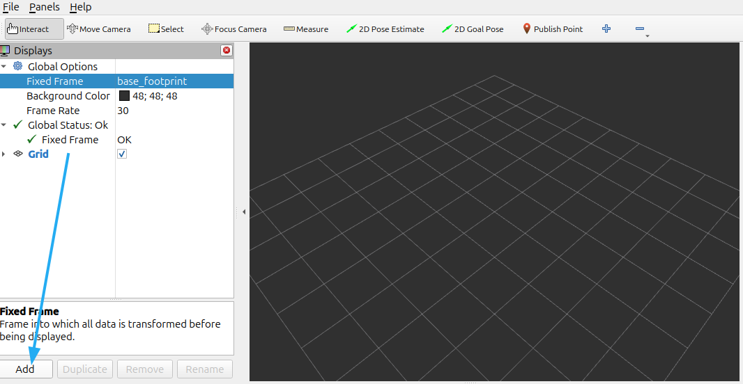
Now we will visualize the robot’s TF frames.
Click:
Add
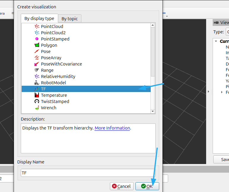
In the plugin selection window, select:
TF
and click:
OK
select TF and click on OK
Visualize the Robot Frames
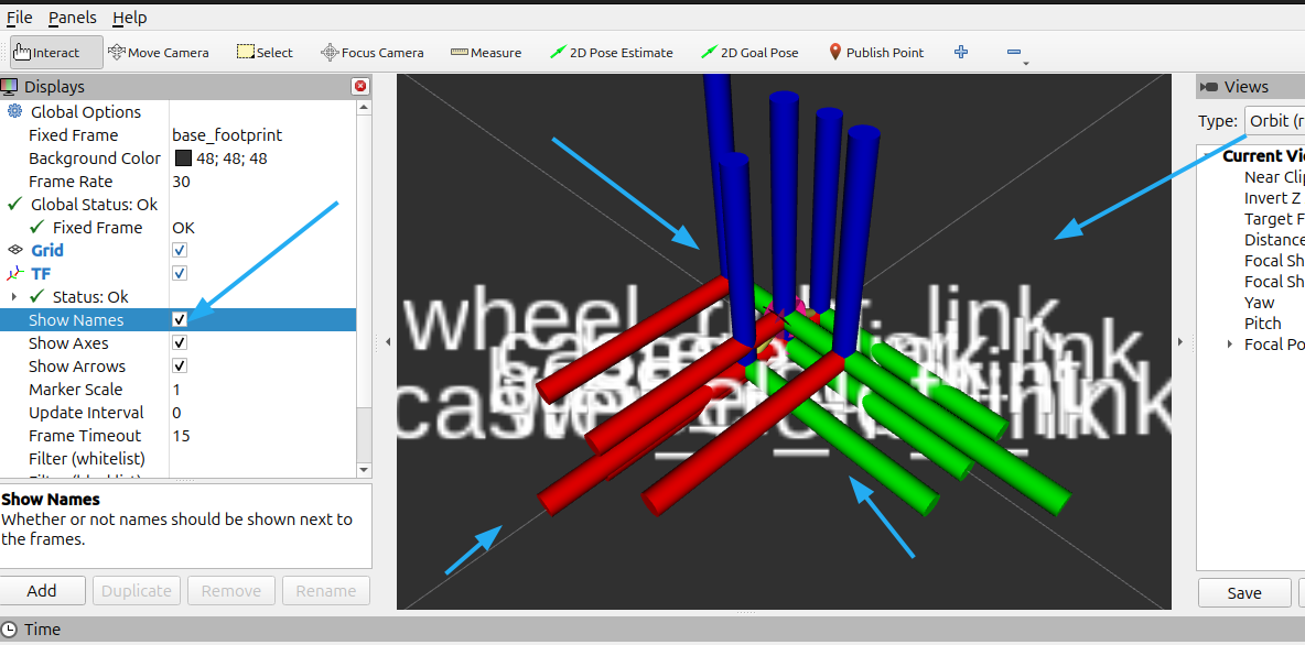
You should now be able to see frames corresponding to different parts of the robot, such as:
base_footprint │ ▼ base_link / \ ▼ ▼wheels caster wheels
The TF information represents the position and orientation of the robot’s different links/frames.
The TF plugin also provides an option to display the names of the frames.
Enable:
Show Names
Select Individual Frames
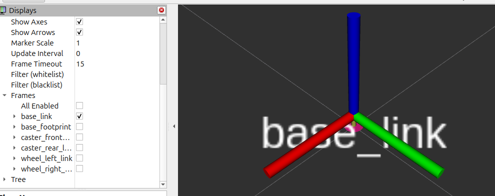
The TF plugin also allows you to control which frames are displayed.
Go to the Frames section of the TF plugin.
You can hide or show individual frames depending on what you want to inspect.
This can be useful when the robot has many frames and the visualization becomes difficult to read.
Add the Robot Model Plugin
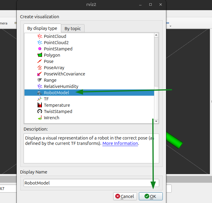
The TF plugin shows the robot’s frames, but we also want to see the actual robot meshes.
For this, we need the:
RobotModel
plugin.
Click:
Add
Select:
RobotModel
and click:
OK
Configure the Robot Model

After adding the RobotModel plugin, we need to tell it where the robot description is coming from.
In the RobotModel settings, find:
Description Source
Set it to:
Topic
Then select the robot description topic:
/robot_description
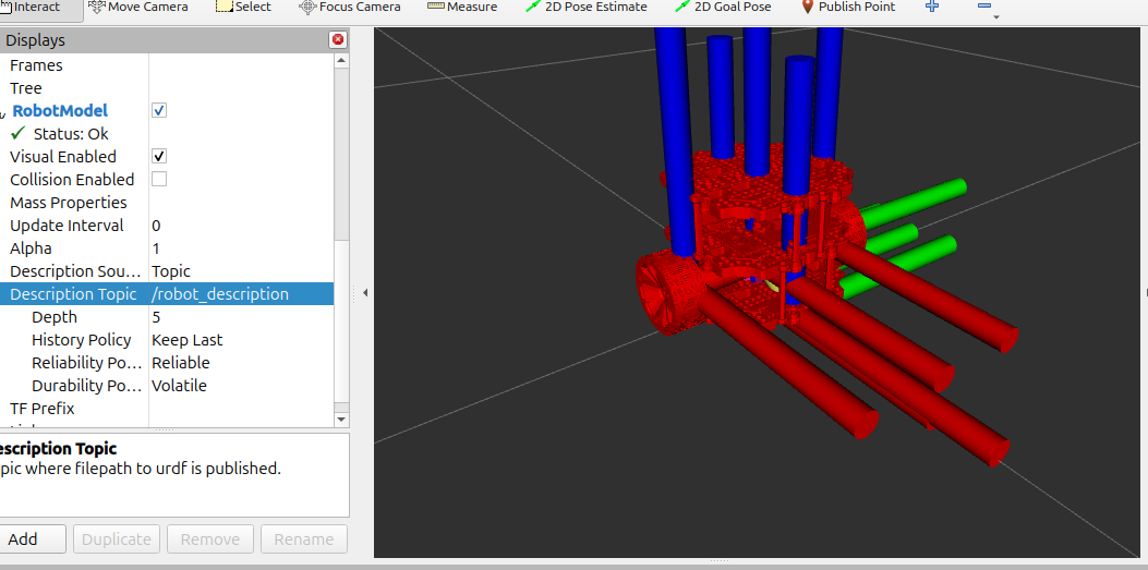
Once /robot_description is selected, RViz2 can use the robot description to display the robot model.
Move the Robot Using Joint State Publisher GUI
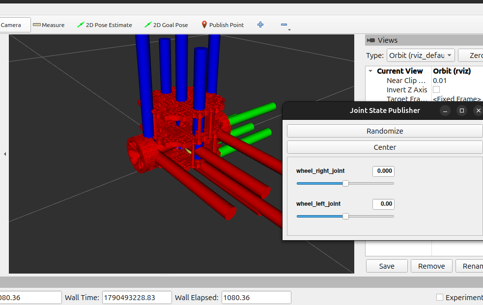
We can now use the joint_state_publisher_gui that we started earlier.
For example, moving the:
wheel_right_joint
slider changes the rotation of the right wheel.
Similarly, moving:
wheel_left_joint
changes the rotation of the left wheel.
Save the RViz2 Configuration

At this point, we have configured RViz2 with:
base_footprintas the Fixed Frame- TF plugin
- RobotModel plugin
/robot_descriptionas the RobotModel source- Our desired frame visibility settings
It would be inconvenient to configure all of this again every time we start RViz2.
So we can save the configuration.
Go to:
File → Save Config As
Navigate to:
bumperbot_ws/src/bumperbot_description/rviz
Save the configuration as:
display.rviz
Your file will be located at:
/home/techarcanist/bumperbot_ws/src/bumperbot_description/rviz/display.rviz
Recommended folder structure
bumperbot_description/├── urdf/│ └── bumperbot.urdf.xacro│└── rviz/ └── display.rviz
The display.rviz file stores the RViz2 visualization configuration we just created.