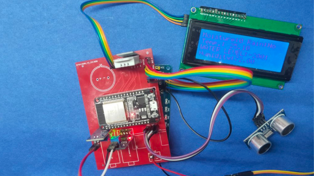
Features
- Capacitive & Resistive Soil Moisture Sensors: Monitor soil moisture levels for efficient watering
- DHT22 Sensor: Tracks temperature and humidity around plants
- Rain Sensor: Detects rainfall to prevent overwatering
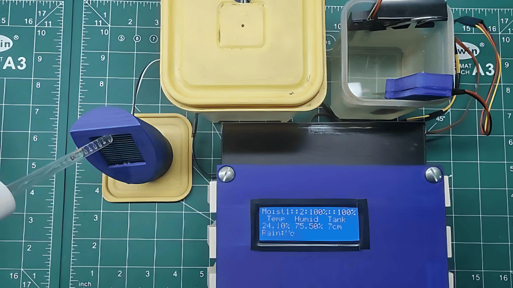
- LCD Display: Provides real-time data visualization
- Automated Watering: Waters plants based on sensor readings
- Water Tank Level Monitoring: Ensures the system knows available water supply
- Database Logging: Stores sensor data in Google Spreadsheets for analysis
- 4 Automated Sockets: Control water pumps or fertilizer pumps independently
- Manual Override Switch: Allows manual control in case of circuit failure
- Remote Monitoring & Control: Accessible through Blynk IoT app
Components Used
- ESP32 (Microcontroller)
- Capacitive and Resistive Soil Moisture Sensors
- DHT22 Sensor (Temperature and Humidity)
- Rain Sensor
- LCD Display
- Water Pump
- Relay Module
- Jumper Wires
- Power Supply
- Buzzer
- Ultrasonic Sensor
How it Works
The ESP32 acts as the brain of the system, continuously gathering data from soil moisture, temperature, humidity, rain, and water tank level sensors. Based on these readings:
- If soil moisture falls below the set threshold and no rainfall is detected, the ESP32 automatically activates the water pump through one of the 4 controllable sockets.
- The sockets can also be configured to drive fertilizer pumps, enabling automated nutrient delivery.
- A manual override switch is included, allowing direct pump control in case of system or circuit failure.
- Sensor readings and pump activity are displayed on the LCD screen for real-time feedback.
- All collected data is logged into Google Spreadsheets, creating a live database for monitoring plant health trends and analyzing irrigation efficiency.
- Remote monitoring and control are possible via the Blynk IoT app, giving users flexibility to supervise and adjust the system from anywhere.
Working
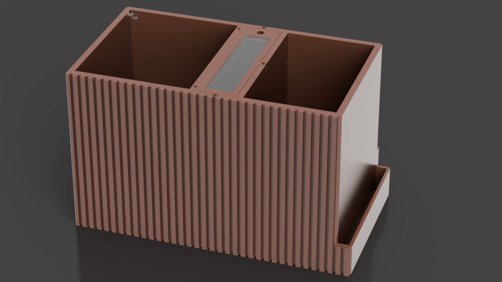
What started on a breadboard now runs as a robust prototype, powered by a custom PCB and secured inside a custom 3D-printed case.
2nd Prototype
1st Prototype
Code & Installation
The complete source code, circuit diagrams, and step-by-step installation instructions are available in the GitHub repository.
Prototype & Files
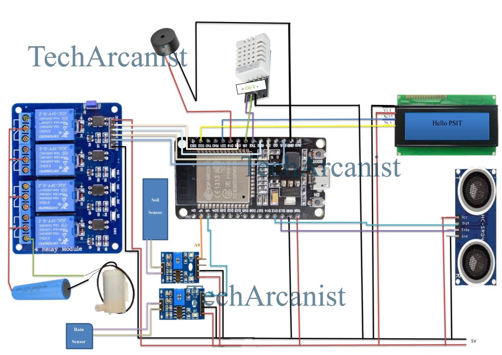
Circuit Diagram
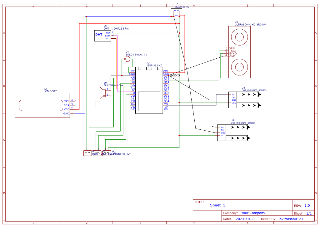
My First Schematic
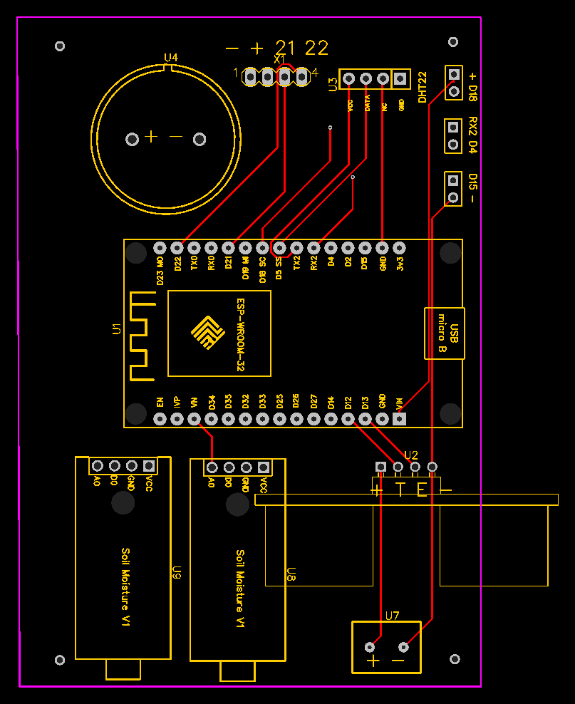
PCB Layout
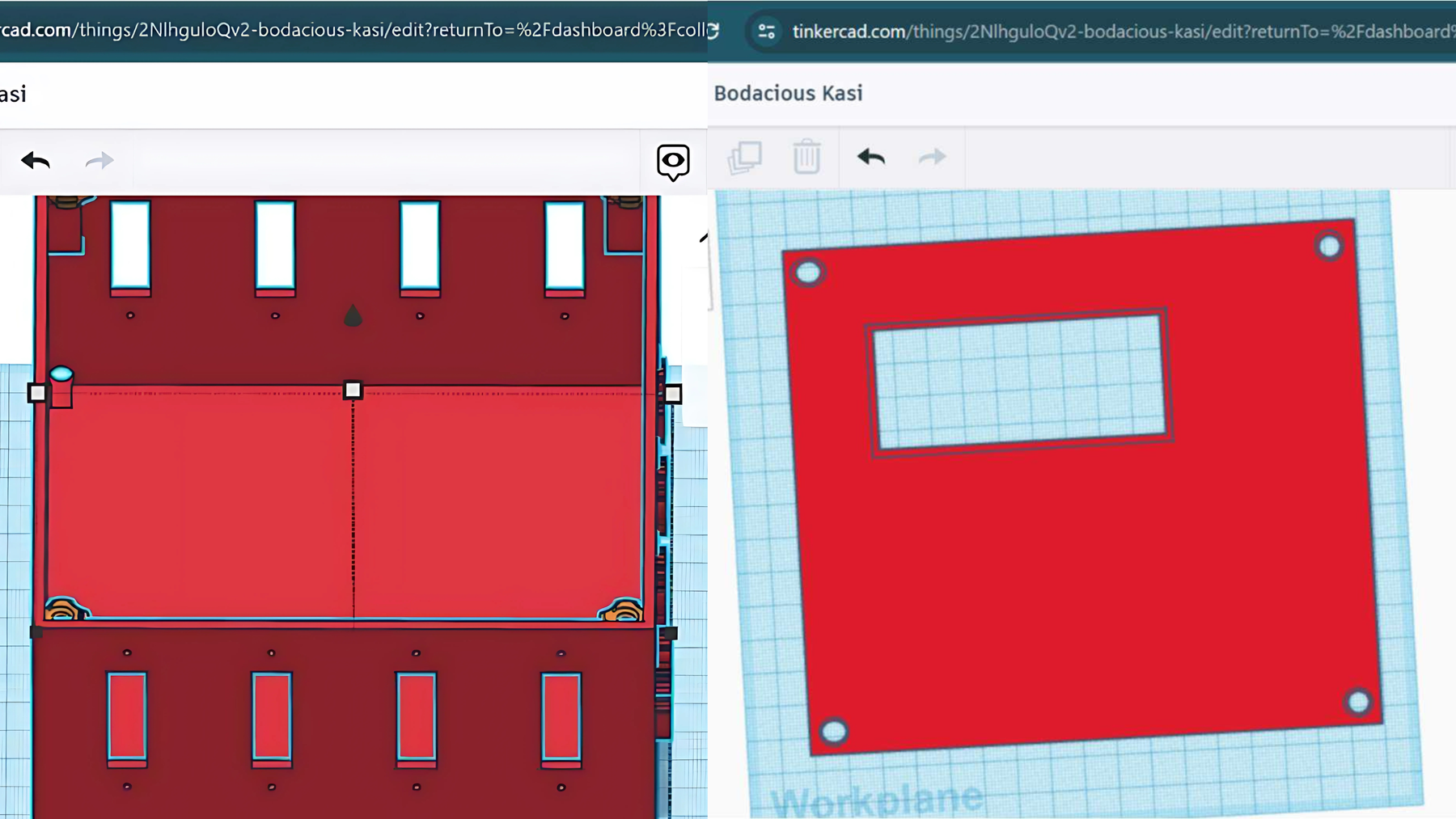
CAD Design on TinkerCAD
My Learnings
- Designed the product using CAD and created physical prototypes using 3D printing
- Designed electronic schematics and PCB layouts, and generated Gerber files for fabrication
- Ordered and assembled my first custom PCB and integrated all components
- Built and tested a fully functional beta version of the product